


Resection in Plane Table Surveying
This method of Resection is used for establishing the instrument stations only. After mixing the stations, details are located either by radiation or intersection. The characteristic feature of resection is that the point plotted on the plan is the station occupied by the plane table.
Cases of Resection in Plane Tabling
There are two cases of resection in plane table surveying;
- The Two-point Problem Resection
- The Three-point Problem Resection
The Two-point Problem Resection
The two-point problem consists of locating the position on the plan of the station occupied by the plane table using observations of two well-defined points visible from the instrument station and whose works have already been plotted on the graph.
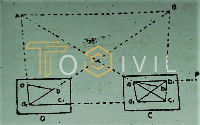
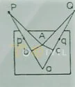
In the given figure, A and B are the two points on the ground, a and b are plotted positions on the plan, C is the station over which the table is to be set up, and its works on the project where it is required to be located. The solution to the problem requires two instrument stations.
The answer is obtained as follows:
- Choose a suitable auxiliary point D so that the angles CAD and CBD are manageable for good intersections at A and B.
- Set up the table at D and level it. Orient the table by compass or judging ab to be parallel to AB and clamp it.
- With the alidade touching sight A, draw a ray through a. Similarly, with the alidade against b, sight B, and draw a ray through b, intersecting the ray drawn through an at d₁, which approximately represents the station D as the orientation is approximate.
- With the alidade centered on d, sight C, and draw a ray d₁c₁ through d, estimating the position of C₁.
- Remove the table, set it up at C with c, over C, and level it. Orient the table parallel to its position at D by backsighting on D. To do this, place the alidade along c, d, and rotate the table until D is bisected. Clamp the table.
- With the alidade against a sight A, draw a ray through a, intersecting the line d₁c, in c₁. With the alidade touching c₁, sight B, and draw a glow through c₁. This ray will pass through b, provided the initial orientation of the table at D was correct. But since the exposure at D and C, although consistent, was only approximate, the rays c and B will not pass through b. Mark the point of intersection b₁ of ₁ B and d, b. The point b₁ thus represents B. Hence ad₁c1b₁ represents ADCB. But since ab is the accurate representation of AB, the error in the initial orientation is equal to the angle b, ab between the lines ab and ab₁. To eliminate the error, the table must be rotated through this angle.
- To do this, Place the alidade along ab, and fix a ranging rod P at a great distance from the table in the line ab, produced.
- Place the alidade along the ab and turn the table until the ranging rod P is bisected. Clamp the table. Ab is parallel to AB, and the table’s orientation is correct.
- To find the proper position of C, center the alidade on a and sight A. Draw a ray through a. Similarly, with the alidade touching b, sight B, and draw a glow through b. The intersection of these two rays gives the proper position (c) on the plan of station (C) occupied.
The Three-point Problem Resection
The three-point problem consists in locating on the plan the position of the instrument station on the ground using observations of three well-defined points whose works have already been plotted on the graph.
Suppose A, B, and C are the three points plotted as a, b, and c on the plan, and the table is set up at T, from which A, B, and C are visible. It is required to plot the position t of the instrument station T on the plan.
The problem may be solved by
- mechanically
- graphically
- by trial
Mechanical Method of Resection
The method is also known as the Tracing-cloth or paper method.
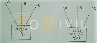
- The table is set up at T and oriented as nearly in its proper position as possible by eye or by compass and clamped. A sheet of tracing cloth or paper is stretched over the plane table sheet (or plan), and a point is chosen on the tracing fabric to represent approximately the station (T) occupied
- When the alidade is centered on t₁, the signals at A, B, and C are sighted successively, and the rays are drawn.
- The tracing cloth is then unfastened and moved over the plane table sheet until the three rays simultaneously pass through the plotted position a, b, and c on the sheet. The point t is then pricked on the sheet with a fine needlepoint. This point thus obtained on the sheet corresponds to the instrument station T.
- The alidade is then placed along ta, and the table is oriented by turning the board until the signal at A is bisected. As a check, points B and C should be sighted with the alidade pivoted on six and c, respectively, and the rays are drawn. These rays should now pass through t if the work is correct. If not, a small error triangle will result, and it may be eliminated by the trial and error method.
Graphical Method of Resection
Bessel’s Solution of the inscribed quadrilateral is the simplest and most commonly used of the several graphical methods.
Bessel’s Method
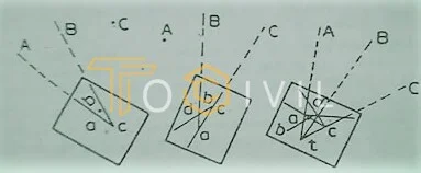
- Having set up and leveled the table, the alidade is placed along the line ca, and the board is turned until A is sighted, a being towards A. The table is then clamped. With the alidade centered on c, B is sighted, and a ray cB is drawn along the edge of the alidade.
- With the alidade placed along ac, the board is turned until the line of sight bisects C, c being towards C, and then clamped. With the alidade touching a, B is sighted, and a ray AB is drawn through a, intersecting the previous ray through c. in point d.
- With the alidade along bd, the table is turned until B is bisected and clamped. The table is now oriented, and t must lie on db, Aa, and Cc. With the alidade centered on a, A is bisected, and a ray is drawn through a, intersecting the ray bd in t, representing the instrument station T.
- The alidade is pivoted to check the orientation, and C is bisected. The ray Ce should now pass through t if the work is correct.
By Trial Method of Resection
The method is known as trial and error or triangle of error method. It is quick and accurate. In this method, the proper position on the plane table sheet of the station occupied is found by trial. After having set up and leveled the instrument, it is oriented as nearly as possible by eye or by the compass and the rays Aa, Bb, and Cc, i. e. resection lines from the three points A, B, and C through the corresponding plotted points a, b, and care then drawn through a, b, and c by sighting to the points A, B, and C.
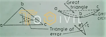
As the table is not correctly oriented, these rays will not pass through one point but will form a small triangle known as the triangle of error. Repeated trials eliminate this triangle so that the three beams, Aa, Bb, and Cc, will finally intersect at a point, which is the correct location of the instrument station on the sheet. The following rules are known as
Lehmann’s rules should be applied in locating the position of “the point sought,” which means the right place on the station’s sheet occupied.
The observer is assumed to face the signals at distant points, and the right and left directions are determined accordingly. The triangle whose vertices are the three fixed points A, B, and C is called the great triangle, while the circle passing through A, B, and C is known as the great circle.
Lehmann’s Rule
- (The distance of the point sought (t) from each of the rays, Aa, Bb, and Cc, is proportional to the length of A, B, and C from T, respectively (or the corresponding plotted distance).
- When looking in the direction of the reference points, the point sought (t) is on the same side of each of the three rays Aa, Bo, and Co, i. e. it is either to the right or to the left, of each of the three rays.
- It follows from rules 1 and 2 that if the instrument station T is outside the great triangle ABC, the triangle of error falls outside the triangle ABC, and the point sought (t) outsights the triangle of error. When the instrument station T is within the great triangle ABC, the triangle of error falls inside the triangle ABC, and the point sought t must be within the triangle of error.
- Although rules 1 to 3 are sufficient to solve the problem, some more rules are given for further assistance.
- When the instrument station T is outside the great circle, the point sought (t) is always on the same side of the ray drawn to the most distant point as the intersection’ (e) of the other two beams. When the instrument station T is outside the great triangle ABC, but inside the great circle but within one of the three segments of the great process, formed by the sides of the great triangle, the ray drawn towards the middle point lies between the fact sought (t) and the intersection (e) of the other two beams
In practice, the topographer selects an advantageous station from which a good view of the surrounding features can be obtained and sets up the plane table. Then finds concerning the three fixed points whether the instrument station is within the great triangle, outside the great triangle but within one of the three segments of the great circle, outside the great circle. Having decided this, he estimates the position of the point sought by applying the above rules.
With the alidade placed along the line joining and one of the points a, b, or c, the table is oriented by turning the board until the corresponding point is sighted. The other stations are again sighted, and the rays are drawn. These rays will pass through t if the estimated position of t has been correct. If not, a second but smaller triangle of error will be formed, and the process is repeated until the right part of t is determined.
Adjustments of the plane Table in Resection
(1) The surface of the board should be a perfect plane.
Test the accuracy in this respect by applying a straight edge in several directions. Remove high spots by planning or sand papering if the surface is not planned.
(2) The surface of the board should be perpendicular to the vertical axis
Place a spirit level on the table and center the bubble to test the accuracy in this respect. Turn the table through 180° and observe if the drop remains central. If not, correct half the apparent error by inserting a packing or a washer between the underside of the board and its support. Relevel the instrument and place the spirit level at right angles to its previous position. Repeat the test and adjustment. Repeat the process until the bubble remains central in all directions on reversal.
(3) The fiducial (or ruling) edge of the alidade should be a straight line
test by drawing a fine line along the fiducial edge of the alidade. Reverse the alidade end for end and put it against the lots of the line. Draw a line along the edge. If the two lines coincide, the alidade is straight. If not, correct the edge by filing, and repeat the test until the edge is valid.
(4) The axes of the spirit levels mounted on the alidade should be parallel to the base of the alidade rule.
To test the accuracy in this respect:
- Place the alidade on the table and bring the bubble of one of the levels to the center of its run using the leveling screws.
- Draw a line against the edge of the ruler.
- Lift and reverse the alidade end for end and replace it against the same. If the bubble is central, the adjustment is correct.
- If not, bring the neli bubble halfway back by the level tube adjusting screws and the remainder by the leveling screws. The second level tube may be tested and adjusted similarly.
5, The sight vanes of the alidade should be perpendicular to the base of the ruler.
Test: Level the table, Suspend a plumb line a short distance from the instrument, and see if the sighting slit and hair appear parallel to the vertical line.
Correction: If not, insert some packing under the base of the sight vanes or file it.
In the case of the telescopic alidade, conditions of adjustment are :
- The line of collimation must be perpendicular to the horizontal axis of the telescope.
- The horizontal axis must be parallel to the base of the alidade rule.
- The fiducial edge should be coincident with or parallel to the collimation plane.
- The bubble line of the telescope level must be parallel to the collimation plane.
- The vertical circle should read zero when the line of collimation is horizontal.
Errors in Plane Tabling
The following are the chief sources of error:
- The board not being horizontal.
- The table needs to be accurately centered.
- The table needs to be correctly oriented.
To guard against this error, the table’s orientation should be checked at as many stations as possible by sighting a distant and prominent object which has been previously plotted.
- The table rotates between sights due to insufficient clamping. The orientation should be checked after the observations at a station are completed.
- The objects are not being sighted accurately.
- The alidade is not correctly centered on the station point on the paper.
- The rays are not accurately drawn through the station point.
- Inaccuracy in plotting.
- The expansion and contraction of the paper.
Error due to Inaccurate Centering
As already explained, the point plotted on the paper should be exactly over the station on the ground, which it represents. The centering and orientation of the table have to be performed simultaneously, which necessitates several trials and causes excellent waste of time. Therefore, to avoid unnecessary loss of time, the surveyor should have a proper conception of the nature and extent of the error caused by inaccurate centering.
Formula of correction
Sin x = Ab/Ap or Sin-1 Ap/Ap ; Sin y = Ar/Aq or y = Sin-1 Ar/Aq
The angular error ( PAQ – PaQ ) = x+y
In practice, with a table 60 cm square, the perpendiculars Ab and Ac seldom exceed 30 cm. The values of x and y, and also of the angular error (x+y) for equal lengths of sights, are given below:
| Length of sight in(m) | Length of Ab o Ac in(m) | Value of x & y | Angular error x+y |
| 30 | 0.30 | 34’30” | 1o9′ |
| 100 | 0.30 | 10’20” | 20’40” |
| 200 | 0.30 | 5’10” | 10’20” |
| 1000 | 0.30 | 1’2″ | 2’4″ |
But the more important is the error in the positions of p and q. The actual position of p will be at p1 to the left of p and q at q₁ to the right of q. The displacement of p =pp₁= ap * x and that of q = qq1= aq x y. These displacements should be too small to be plotted on paper so that the accuracy of the plan will not be affected, and this depends upon the scale of the project. If the project scale is I cm = mm, and Ab =ecm. Then, plotted length
ap = AP/m cm ; Plotted length aq = AQ/m cm
Actual displacement pp1 = AP/m * x cm
Actual displacement qq1 = AQ/m * y cm
whereas pp1 = e/m (cm) =qq1
Now taking 0.025 cm as the limit of precision for plotting
e/m =1/40 or e = m/40
e must not exceed e/40
Very accurate centering is not necessary except for short sights when the scale is smaller than 24m to 1 cm, in which case it is sufficient to have the station peg somewhere below the table, but it is essential when the scale is large. However, it is desirable to center the table as accurately as possible without wasting time.
More Articles